Repurposed 18650 Batteries into a power station – pt1.2
Part 1.2 : Progress on the charger/discharger
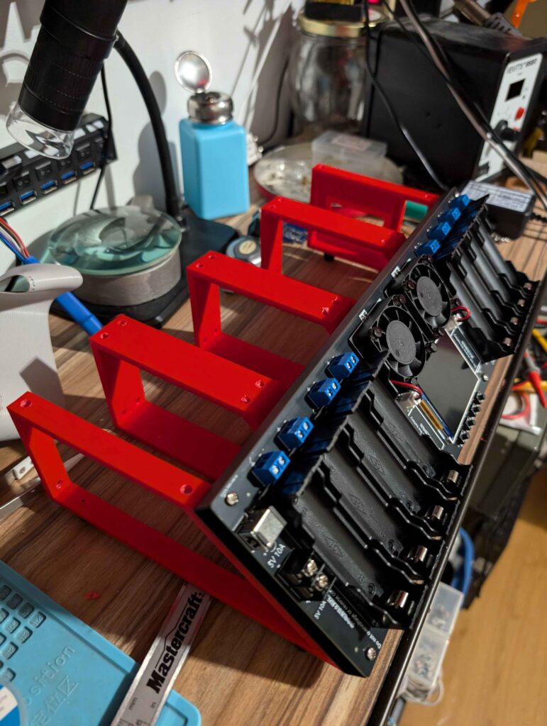
So, since I needed to make a charger and discharger to test the tons of 18650s I’ll have to deal with, I decided to make it convenient. plus the form factor of the discharger is a bit odd to work with. At this point, I designed a frame to hold the tester, 8 charge circuits with their battery holder, a PSU underneath and a decent power connector. I wanted everything to be in a neat package, carry-able and solid, so I went for a design that was kinda modular to save on plastic and that would be easier to print.
This came with a few problems that required some redesign and reprints but nothing outstanding. Here’s some details of the progress so far.
First off I started with the outside frames as they needed to be perfect fits with the actual tester. The first one was rather easy to make since it was the frame and the holes, that’s it ( I still forgot the feet but that’s a post process thing I solved by just drilling and screwing them). Also, enjoy a quick preview of all the frames together. 🙂
Next came to the back braces. These were super easy to make but, sizing issue resulted in them being all unusable. They’re in the queue to be reprinted as of this writing.

Still not entirely discouraged, I worked on the top plates for the chargers, which were a real piece of puzzle but I’m glad how it came out. Before putting them together I had to remove the USB connector from each of the charge circuits. It was a bit painful but totally worth it. I was really glad the hot air iron was around, and my flux and copper wick made the rest of the job way less painful. Each circuits was re-tested after the removal to ensure they were pushing the right power out. never know what could happen.
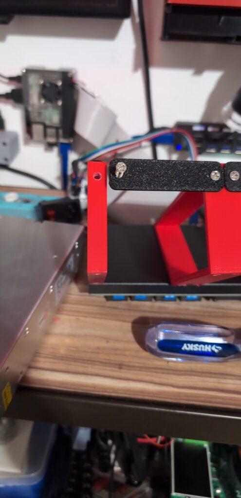
Once I had every charge circuits ready, it was time to print and assemble the charge plates. So far, only one has been done but it should be pretty much the same. I started by testing the fit of everything, which was pretty satisfying to see it going together properly. Then I realized that not all charge circuits have the center hole that I was planning to use to secure them on the plate so I had to improvise. I found a bunch of old pins that I recovered from a LCD screen connector, these will do perfect to poke in the plastic and hold everything in place with the plastic tabs melted on the board. And once all the questions were answered, I finally assembled the first plate and put it on the frames. I’m very happy with the result even tho it’s not perfect, it’ll be very helpful.
Now the only part left for this to be usable is to install the power connector and the PSU, and wire everything, which should be ready soon hopefully!
To be continued…


